

[gelöst] Schaltzustand Verzögern
-
@Aphofis sagte:
Wo das Magnetventil novh direkt über den Schwimmschalter lief, gab es keine Ausfälle.
Wie wird jetzt der Osmose-Schwimmer elektronisch ausgewertet ? Hat der Schwimmer nur einen Schließer oder einen Wechsler ?
-
@paul53
Die Schwimmer haben je einen 10 kOhm Widerstand in der Minus Leitung zur Steuerleitung zum Esp8266@Aphofis sagte:
einen 10 kOhm Widerstand in der Minus Leitung zur Steuerleitung zum Esp8266
Schaltet der Schwimmer-Kontakt gegen Masse (Minus) ? Ist der 10 kOhm Widerstand eine Pull Up (gegen welche Spannung) oder in Reihe zum Kontakt ?
Bitte verzichtet auf Chat-Nachrichten, denn die Handhabung ist grauenhaft !
Produktiv: Asus PN 42 / N100 / 8 GB / 500 GB; Proxmox mit 2 VM (iob / openCCU) -
@Aphofis sagte:
einen 10 kOhm Widerstand in der Minus Leitung zur Steuerleitung zum Esp8266
Schaltet der Schwimmer-Kontakt gegen Masse (Minus) ? Ist der 10 kOhm Widerstand eine Pull Up (gegen welche Spannung) oder in Reihe zum Kontakt ?
-
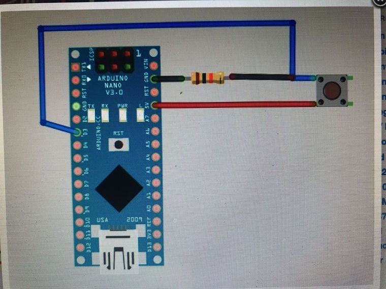
@Aphofis sagte:
Ich denke mal da am esp sind es 3,3 volt
In diesem Bild schaltet der Kontakt gegen +5 V und der Widerstand ist ein Pull down (gegen Masse).
Bitte verzichtet auf Chat-Nachrichten, denn die Handhabung ist grauenhaft !
Produktiv: Asus PN 42 / N100 / 8 GB / 500 GB; Proxmox mit 2 VM (iob / openCCU) -
@Aphofis sagte:
Ich denke mal da am esp sind es 3,3 volt
In diesem Bild schaltet der Kontakt gegen +5 V und der Widerstand ist ein Pull down (gegen Masse).
-
@paul53
Ist nur ein Bild wie es bei mir angeschlossen ist nur ist an 3,3 Volt angeschlossen nicht an 5 Volt@Aphofis
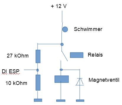
Dann wäre mein Vorschlag:+12 V -- Schwimmer-Kontakt -- Relais-Kontakt -- Magnetventil -- Masse (-12 V)
+12 V -- Schwimmer-Kontakt -- 27 kOhm -- DI (ESP) -- 10 kOhm -- MasseDann würde der Schwimmer direkt auf das Magnetventil wirken, wenn der Relais-Kontakt geschlossen ist und über den Spannungsteiler hat man die Information über den Schwimmerzustand.
Ich denke, dass der ESP eine Schutzbeschaltung für die Eingänge hat ? Der 27 kOhm Widerstand muss dann den Strom bei den hohen Spannungsspitzen begrenzen. Besser ist natürlich eine Freilaufdiode für das Magnetventil.Bitte verzichtet auf Chat-Nachrichten, denn die Handhabung ist grauenhaft !
Produktiv: Asus PN 42 / N100 / 8 GB / 500 GB; Proxmox mit 2 VM (iob / openCCU) -
@Aphofis
Dann wäre mein Vorschlag:+12 V -- Schwimmer-Kontakt -- Relais-Kontakt -- Magnetventil -- Masse (-12 V)
+12 V -- Schwimmer-Kontakt -- 27 kOhm -- DI (ESP) -- 10 kOhm -- MasseDann würde der Schwimmer direkt auf das Magnetventil wirken, wenn der Relais-Kontakt geschlossen ist und über den Spannungsteiler hat man die Information über den Schwimmerzustand.
Ich denke, dass der ESP eine Schutzbeschaltung für die Eingänge hat ? Der 27 kOhm Widerstand muss dann den Strom bei den hohen Spannungsspitzen begrenzen. Besser ist natürlich eine Freilaufdiode für das Magnetventil. -
@Aphofis sagte :
Also meinst du so ???
Nein.
Ist der Schwimmer-Kontakt ein Öffner ? Muss er ja sein, wenn bei Erreichen des Pegels bei direkter Verschaltung das Magnetventil schließt (spannungslos wird).Bitte verzichtet auf Chat-Nachrichten, denn die Handhabung ist grauenhaft !
Produktiv: Asus PN 42 / N100 / 8 GB / 500 GB; Proxmox mit 2 VM (iob / openCCU) -
@Aphofis sagte :
Also meinst du so ???
Nein.
Ist der Schwimmer-Kontakt ein Öffner ? Muss er ja sein, wenn bei Erreichen des Pegels bei direkter Verschaltung das Magnetventil schließt (spannungslos wird).@paul53
Je nach dem wie ich den Schwimmer einstecke ist oben true oder unten true
Wie gesagt, eine Schaltung kann ich nachbauen! nur die Verbindungen kann ich nur nachbauen wenn ich eine Zeichnung sehe!
Bitte hab Verständnis, ich bin Konstruktionstechniker und kann dir Häuser oder komplexe statische Konstruktionen bauen aber bei Schaltungen in Form von Text ist es mir schwer möglich das zu realisieren. -
@paul53
Also 12 Volt + vom Stepdown gehen in den Schwimmer
anderes Kabel vom Schwimmer geht ans Relais an NO
andere Seite Relais geht in + 12 V Ans Magnetventil
mit am Schwimmer an NO am Relais geht ein 27 kOhm widerstand an Digital Anschluss am ESP und von da in einen 10 kOhm Widerstand und dann ins Magnetventil Minus -
@paul53
Also 12 Volt + vom Stepdown gehen in den Schwimmer
anderes Kabel vom Schwimmer geht ans Relais an NO
andere Seite Relais geht in + 12 V Ans Magnetventil
mit am Schwimmer an NO am Relais geht ein 27 kOhm widerstand an Digital Anschluss am ESP und von da in einen 10 kOhm Widerstand und dann ins Magnetventil Minus@Aphofis sagte in Schaltzustand Verzögern:
von da in einen 10 kOhm Widerstand und dann ins Magnetventil Minus
Der 10 kOhm Widerstand gegen Masse (GND) ist ja bereits vorhanden.
Bitte verzichtet auf Chat-Nachrichten, denn die Handhabung ist grauenhaft !
Produktiv: Asus PN 42 / N100 / 8 GB / 500 GB; Proxmox mit 2 VM (iob / openCCU) -
@Aphofis sagte in Schaltzustand Verzögern:
von da in einen 10 kOhm Widerstand und dann ins Magnetventil Minus
Der 10 kOhm Widerstand gegen Masse (GND) ist ja bereits vorhanden.
@paul53
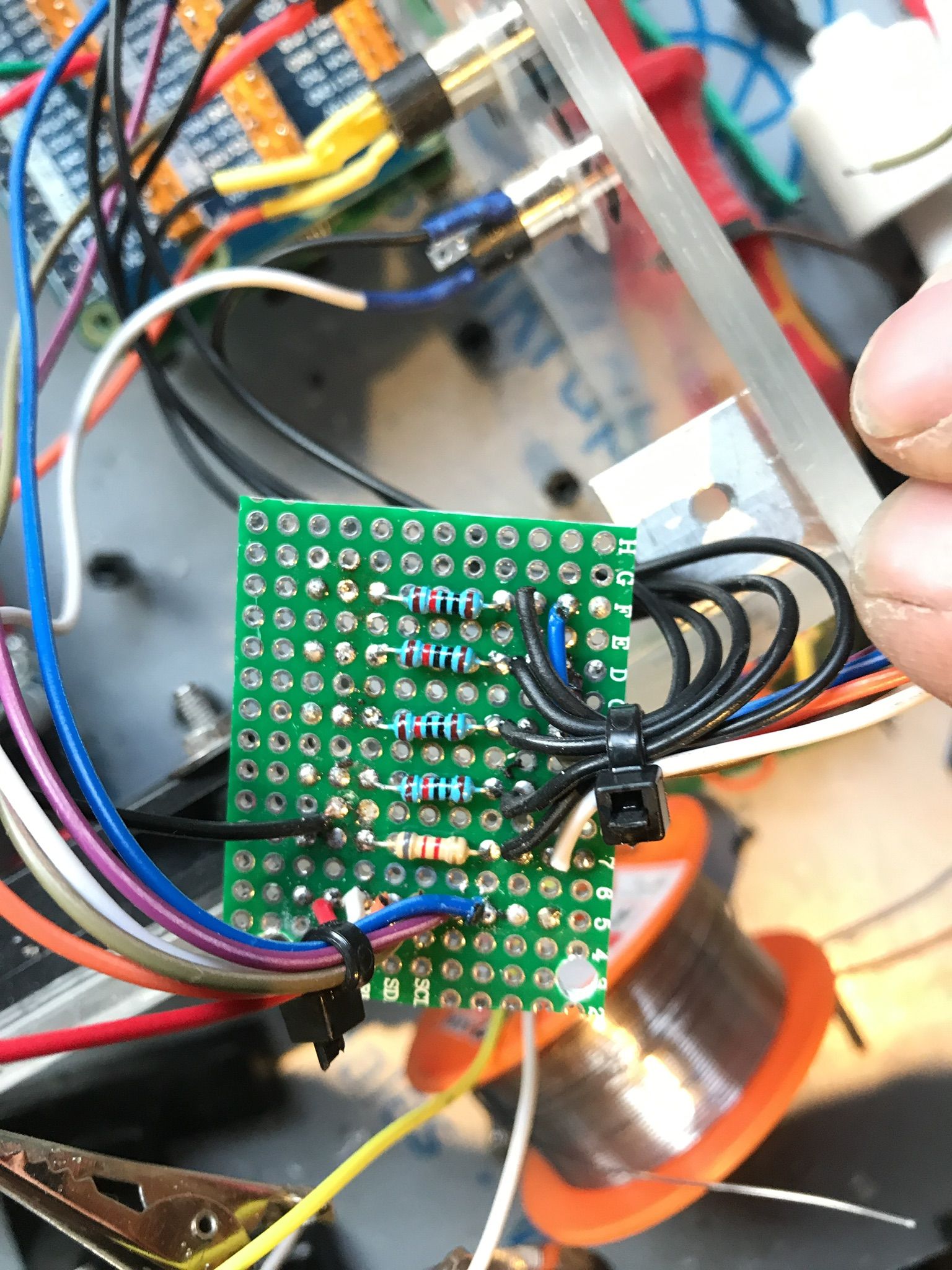
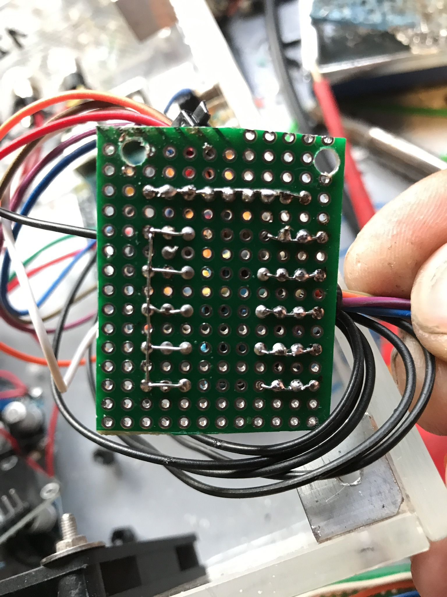
Naja ich muss dann eine neue Platine für die Widerstände bauen bzw nicht wenn die 27 kOhm Widerstände mit auf die Karte passen.
Das mache ich aber nur beim Osmose Schwimmer!?
Da ja alle anderen Schwimmer einwandfrei funktionieren.
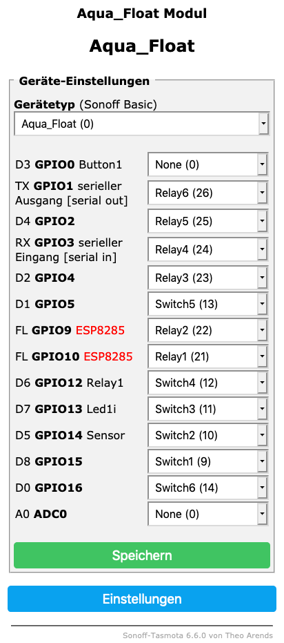
An der Tasmota Einstellung kann alles so bleiben ??? -
@paul53
Naja ich muss dann eine neue Platine für die Widerstände bauen bzw nicht wenn die 27 kOhm Widerstände mit auf die Karte passen.
Das mache ich aber nur beim Osmose Schwimmer!?
Da ja alle anderen Schwimmer einwandfrei funktionieren.
An der Tasmota Einstellung kann alles so bleiben ???@Aphofis sagte:
Das mache ich aber nur beim Osmose Schwimmer!?
Ja, ist an anderer Stelle nicht nötig.
@Aphofis sagte in Schaltzustand Verzögern:
An der Tasmota Einstellung kann alles so bleiben ???
Wenn der Schwimmer-Kontakt vorher auch bei Erreichen des Pegels, bei dem das Magnetventil schließt, geöffnet wurde: Ja.
Bitte verzichtet auf Chat-Nachrichten, denn die Handhabung ist grauenhaft !
Produktiv: Asus PN 42 / N100 / 8 GB / 500 GB; Proxmox mit 2 VM (iob / openCCU) -
@Aphofis sagte:
Das mache ich aber nur beim Osmose Schwimmer!?
Ja, ist an anderer Stelle nicht nötig.
@Aphofis sagte in Schaltzustand Verzögern:
An der Tasmota Einstellung kann alles so bleiben ???
Wenn der Schwimmer-Kontakt vorher auch bei Erreichen des Pegels, bei dem das Magnetventil schließt, geöffnet wurde: Ja.
-
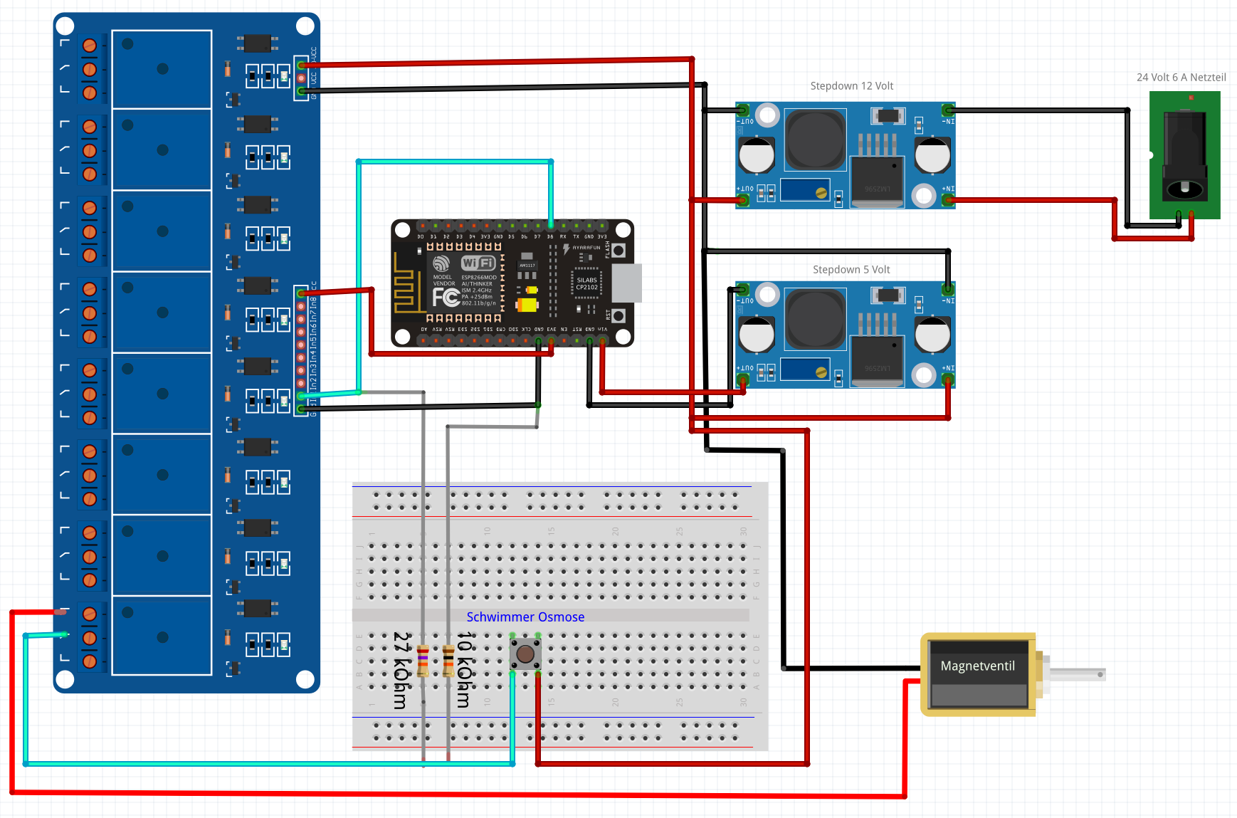
@Aphofis sagte:
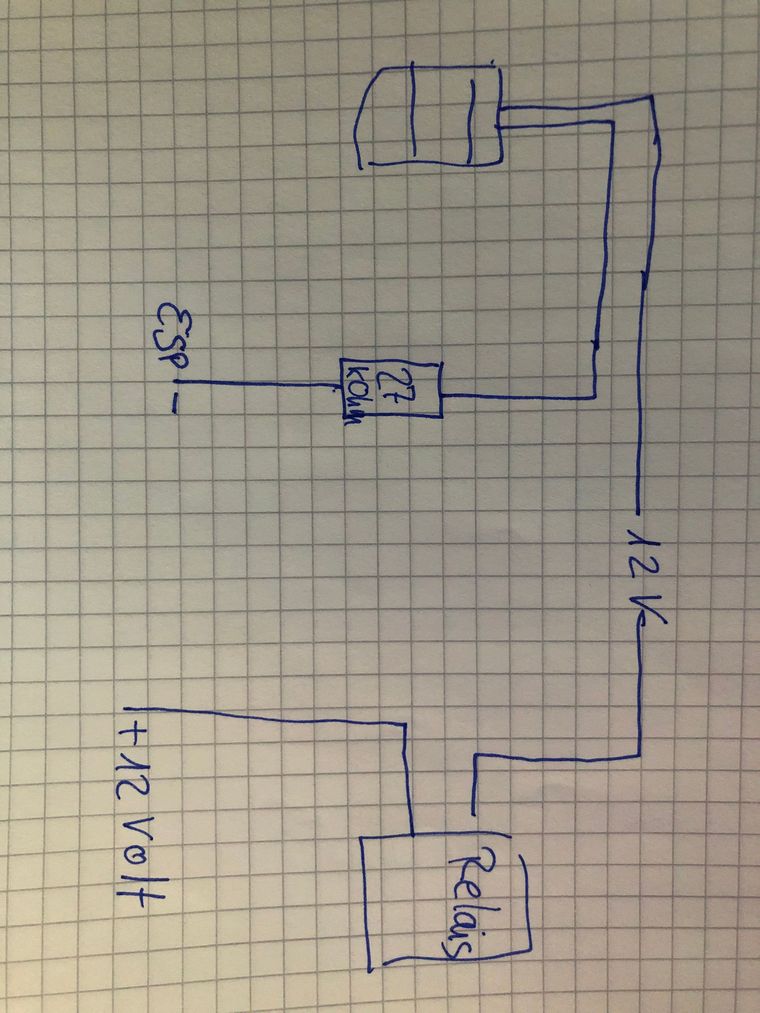
Wäre es so korrekt !?
Nein, der 10 kOhm Widerstand muss parallel zum ESP-Eingang wirken, nicht am Schwimmer-Kontakt. Weshalb ist der 27 kOhm Widerstand auf das Relais-Board geschaltet (türkise Verbindung zwischen Relais-Board und ESP) ?
Bitte verzichtet auf Chat-Nachrichten, denn die Handhabung ist grauenhaft !
Produktiv: Asus PN 42 / N100 / 8 GB / 500 GB; Proxmox mit 2 VM (iob / openCCU) -
@Aphofis sagte:
Wäre es so korrekt !?
Nein, der 10 kOhm Widerstand muss parallel zum ESP-Eingang wirken, nicht am Schwimmer-Kontakt. Weshalb ist der 27 kOhm Widerstand auf das Relais-Board geschaltet (türkise Verbindung zwischen Relais-Board und ESP) ?
@paul53
Weil ich es so verstanden hatte!!!Osmose Schwimmer Fritzing
Wenn du fritzing hast, kannst du es vielleicht korrigieren!? -
@paul53
Weil ich es so verstanden hatte!!!Osmose Schwimmer Fritzing
Wenn du fritzing hast, kannst du es vielleicht korrigieren!? -
@paul53
Oha
Das was du auf dem Bild siehst um Schaltpläne zu erstellen
Ich kann wie gesagt schaltungen nach bauen! ich weiß nicht genau wo die Widerstände angelötet werden müssen.
Wenn du mir das etwas genauer erklären kannst, dann baue ich den Osmose Schwimmer so um !!!
Hey! Du scheinst an dieser Unterhaltung interessiert zu sein, hast aber noch kein Konto.
Hast du es satt, bei jedem Besuch durch die gleichen Beiträge zu scrollen? Wenn du dich für ein Konto anmeldest, kommst du immer genau dorthin zurück, wo du zuvor warst, und kannst dich über neue Antworten benachrichtigen lassen (entweder per E-Mail oder Push-Benachrichtigung). Du kannst auch Lesezeichen speichern und Beiträge positiv bewerten, um anderen Community-Mitgliedern deine Wertschätzung zu zeigen.
Mit deinem Input könnte dieser Beitrag noch besser werden 💗
Registrieren AnmeldenSupport us
586
Online33.0k
Benutzer83.4k
Themen1.3m
Beiträge