Navigation

    Logo
    • Register
    • Login
    • Search
    • Recent
    • Tags
    • Unread
    • Categories
    • Unreplied
    • Popular
    • GitHub
    • Docu
    • Hilfe
    1. Home
    2. Deutsch
    3. Skripten / Logik
    4. Blockly
    5. [gelöst] Schaltzustand Verzögern

    NEWS

    • Wir empfehlen: Node.js 22.x

    • Neuer Blog: Fotos und Eindrücke aus Solingen

    • ioBroker goes Matter ... Matter Adapter in Stable

    [gelöst] Schaltzustand Verzögern

    This topic has been deleted. Only users with topic management privileges can see it.
    • Aphofis
      Aphofis last edited by

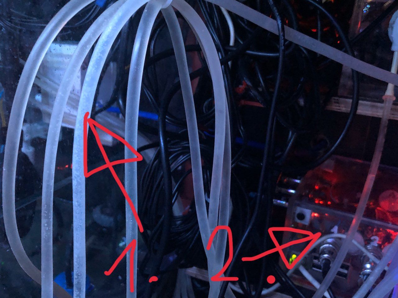
      12B8F773-B5E4-48B4-ACDF-3991ED2483BC.jpeg

      1. Magnetventil
      2. Stecker Anschluss 12 Volt +/- zum magnetventil
      1 Reply Last reply Reply Quote 0
      • paul53
        paul53 @Aphofis last edited by

        @Aphofis sagte:

        bis zum magnetventil ein geschirmtes USB kabel nehmen

        Leitungsquerschnitt ausreichend ?

        Aphofis 1 Reply Last reply Reply Quote 0
        • Aphofis
          Aphofis @paul53 last edited by

          @paul53
          2x 0,75 ist Plus
          1x 0,75 ist Minus

          Aphofis 1 Reply Last reply Reply Quote 0
          • Aphofis
            Aphofis @Aphofis last edited by Aphofis

            Von der Buchse intern gehen normale Steuerleitungen je 1x 0,75 zum Relais und ans Minus vom Stepdown

            1 Reply Last reply Reply Quote 0
            • paul53
              paul53 @Aphofis last edited by

              @Aphofis sagte:

              Minus vom Magnetventil geht zu einem Sammel Minus zurück
              2x 0,75 ist Plus
              1x 0,75 ist Minus

              Ich würde eher die Masseleitung (Minus) doppelt nehmen.

              Meine Frage nach dem ausreichenden Querschnitt bezog sich aber auf das USB-Kabel.

              Aphofis 1 Reply Last reply Reply Quote 0
              • Aphofis
                Aphofis @paul53 last edited by

                @paul53
                Keine Ahnung was ein USB Kabel für einen Kabel Querschnitt hat!
                Es sind ja min. 4 Adern ich kann ein USB Kabel einbauen und intern 1,25 qmm nehmen als leitungen zum Relais und zum Stepdown.

                1 Reply Last reply Reply Quote 0
                • paul53
                  paul53 @Aphofis last edited by

                  @Aphofis sagte:

                  Wo das Magnetventil novh direkt über den Schwimmschalter lief, gab es keine Ausfälle.

                  Wie wird jetzt der Osmose-Schwimmer elektronisch ausgewertet ? Hat der Schwimmer nur einen Schließer oder einen Wechsler ?

                  Aphofis 2 Replies Last reply Reply Quote 0
                  • Aphofis
                    Aphofis @paul53 last edited by

                    @paul53
                    Die Schwimmer haben je einen 10 kOhm Widerstand in der Minus Leitung zur Steuerleitung zum Esp8266

                    paul53 1 Reply Last reply Reply Quote 0
                    • Aphofis
                      Aphofis @paul53 last edited by

                      @paul53
                      Der ESP zeigt im unteren bereich in der Tasmota Oberfläche true also 1 an und im oberen bereich false also 0

                      Konfiguriert sind Die Schwimmer folgendermaßen:

                      Bildschirmfoto 2019-10-04 um 14.35.05.png

                      1 Reply Last reply Reply Quote 0
                      • paul53
                        paul53 @Aphofis last edited by

                        @Aphofis sagte:

                        einen 10 kOhm Widerstand in der Minus Leitung zur Steuerleitung zum Esp8266

                        Schaltet der Schwimmer-Kontakt gegen Masse (Minus) ? Ist der 10 kOhm Widerstand eine Pull Up (gegen welche Spannung) oder in Reihe zum Kontakt ?

                        Aphofis 1 Reply Last reply Reply Quote 0
                        • Aphofis
                          Aphofis @paul53 last edited by Aphofis

                          @paul53
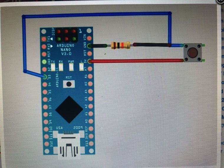
                          Ich denke mal da am esp sind es 3,3 volt
                          665207AB-4D94-4ED6-9D54-AF5083D3B048.jpeg

                          paul53 1 Reply Last reply Reply Quote 0
                          • paul53
                            paul53 @Aphofis last edited by

                            @Aphofis sagte:

                            Ich denke mal da am esp sind es 3,3 volt

                            In diesem Bild schaltet der Kontakt gegen +5 V und der Widerstand ist ein Pull down (gegen Masse).

                            Aphofis 1 Reply Last reply Reply Quote 0
                            • Aphofis
                              Aphofis @paul53 last edited by

                              @paul53
                              Ist nur ein Bild wie es bei mir angeschlossen ist nur ist an 3,3 Volt angeschlossen nicht an 5 Volt

                              paul53 1 Reply Last reply Reply Quote 0
                              • paul53
                                paul53 @Aphofis last edited by paul53

                                @Aphofis
                                Dann wäre mein Vorschlag:

                                +12 V -- Schwimmer-Kontakt -- Relais-Kontakt -- Magnetventil -- Masse (-12 V)
                                +12 V -- Schwimmer-Kontakt -- 27 kOhm -- DI (ESP) -- 10 kOhm -- Masse

                                Dann würde der Schwimmer direkt auf das Magnetventil wirken, wenn der Relais-Kontakt geschlossen ist und über den Spannungsteiler hat man die Information über den Schwimmerzustand.
                                Ich denke, dass der ESP eine Schutzbeschaltung für die Eingänge hat ? Der 27 kOhm Widerstand muss dann den Strom bei den hohen Spannungsspitzen begrenzen. Besser ist natürlich eine Freilaufdiode für das Magnetventil.

                                Aphofis 1 Reply Last reply Reply Quote 0
                                • Aphofis
                                  Aphofis @paul53 last edited by

                                  @paul53

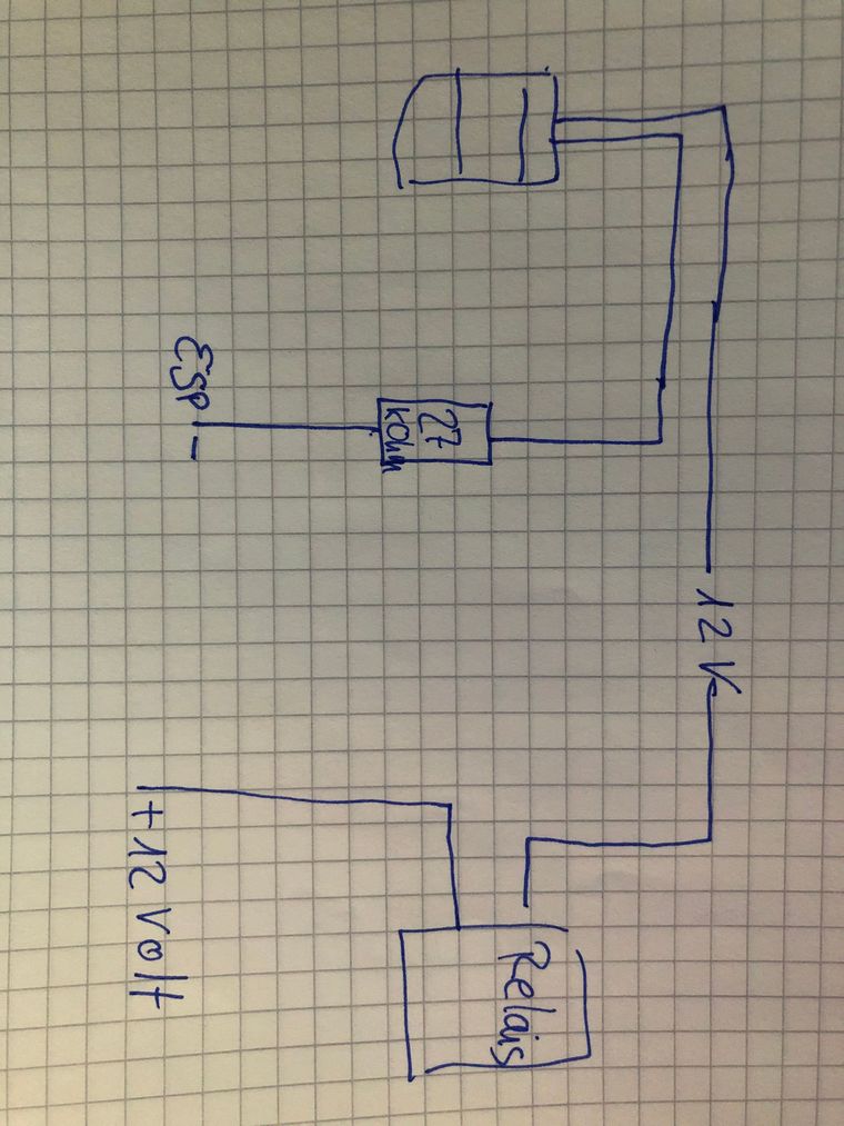
                                  Also meinst du so ???

                                  A1BF932E-4276-4376-BC61-A6373393A1A0.jpeg

                                  paul53 1 Reply Last reply Reply Quote 0
                                  • paul53
                                    paul53 @Aphofis last edited by

                                    @Aphofis sagte :

                                    Also meinst du so ???

                                    Nein.
                                    Ist der Schwimmer-Kontakt ein Öffner ? Muss er ja sein, wenn bei Erreichen des Pegels bei direkter Verschaltung das Magnetventil schließt (spannungslos wird).

                                    Aphofis 1 Reply Last reply Reply Quote 0
                                    • Aphofis
                                      Aphofis @paul53 last edited by

                                      @paul53
                                      Je nach dem wie ich den Schwimmer einstecke ist oben true oder unten true
                                      Wie gesagt, eine Schaltung kann ich nachbauen! nur die Verbindungen kann ich nur nachbauen wenn ich eine Zeichnung sehe!
                                      Bitte hab Verständnis, ich bin Konstruktionstechniker und kann dir Häuser oder komplexe statische Konstruktionen bauen aber bei Schaltungen in Form von Text ist es mir schwer möglich das zu realisieren.

                                      paul53 1 Reply Last reply Reply Quote 0
                                      • paul53
                                        paul53 @Aphofis last edited by paul53

                                        @Aphofis sagte:

                                        wenn ich eine Zeichnung sehe!

                                        Schwimmer_MV_ESP.JPG

                                        Aphofis 1 Reply Last reply Reply Quote 0
                                        • Aphofis
                                          Aphofis @paul53 last edited by

                                          @paul53
                                          Also 12 Volt + vom Stepdown gehen in den Schwimmer
                                          anderes Kabel vom Schwimmer geht ans Relais an NO
                                          andere Seite Relais geht in + 12 V Ans Magnetventil
                                          mit am Schwimmer an NO am Relais geht ein 27 kOhm widerstand an Digital Anschluss am ESP und von da in einen 10 kOhm Widerstand und dann ins Magnetventil Minus

                                          paul53 1 Reply Last reply Reply Quote 0
                                          • paul53
                                            paul53 @Aphofis last edited by

                                            @Aphofis sagte in Schaltzustand Verzögern:

                                            von da in einen 10 kOhm Widerstand und dann ins Magnetventil Minus

                                            Der 10 kOhm Widerstand gegen Masse (GND) ist ja bereits vorhanden.

                                            Aphofis 1 Reply Last reply Reply Quote 0
                                            • First post
                                              Last post

                                            Support us

                                            ioBroker
                                            Community Adapters
                                            Donate

                                            811
                                            Online

                                            32.0k
                                            Users

                                            80.4k
                                            Topics

                                            1.3m
                                            Posts

                                            4
                                            262
                                            16348
                                            Loading More Posts
                                            • Oldest to Newest
                                            • Newest to Oldest
                                            • Most Votes
                                            Reply
                                            • Reply as topic
                                            Log in to reply
                                            Community
                                            Impressum | Datenschutz-Bestimmungen | Nutzungsbedingungen
                                            The ioBroker Community 2014-2023
                                            logo