

S0 - Signal mit Wemos D1 Mini erzeugen?
-
kann keine Funktion/Signalpuls messen
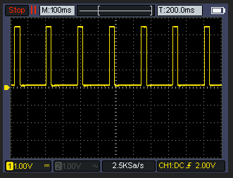
Hab zum Test nochmal ESPEasy zum Vergleich genutzt und hier lässt sich ein Puls messen.
Komisch nochmal das gleiche mit PIN 2
-
Komisch nochmal das gleiche mit PIN 2
bisher nein und mit ESPEasy alles wie gehabt:
Der ESP32S2 ist am seriellen Anschluß etwas speziell, daher sehe ich im Moment keine Log/Terminal Daten ob er überhaupt startet.
Gucke mal ob ich was anderes hier hab.
-
@dieter_p Ich würde das mit Adurino IDE auf einen ESP flashen.
Hier der Code vereinfacht und ohne Wifi & MQTT. Das sollte jetzt 5kwH abbilden.
// S0 Pin configuration const int s0Pin = 7; // Pin connected to the S0 output signal // Timing variables unsigned long pulseDuration = 100; // Duration of each pulse in milliseconds // replaced with static value unsigned long pulseInterval = (3600 * 1000) / (5 * 1000) - pulseDuration; // Interval between pulses in milliseconds (initial value) void setup() { // Set the S0 pin as an output pinMode(s0Pin, OUTPUT); // Initialize Serial for debugging Serial.begin(115200); } void loop() { // Generate a pulse digitalWrite(s0Pin, HIGH); // Set the S0 pin HIGH delay(pulseDuration); // Wait for the pulse duration digitalWrite(s0Pin, LOW); // Set the S0 pin LOW delay(pulseInterval); // Wait for the interval before the next pulse }@andy123andy1 said in S0 - Signal mit Wemos D1 Mini erzeugen?:
// S0 Pin configuration
const int s0Pin = 7; // Pin connected to the S0 output signal// Timing variables
unsigned long pulseDuration = 100; // Duration of each pulse in milliseconds
// replaced with static value
unsigned long pulseInterval = (3600 * 1000) / (5 * 1000) - pulseDuration; // Interval between pulses in milliseconds (initial value)void setup() {
// Set the S0 pin as an output
pinMode(s0Pin, OUTPUT);// Initialize Serial for debugging
Serial.begin(115200);
}void loop() {
// Generate a pulse
digitalWrite(s0Pin, HIGH); // Set the S0 pin HIGH
delay(pulseDuration); // Wait for the pulse duration
digitalWrite(s0Pin, LOW); // Set the S0 pin LOW
delay(pulseInterval); // Wait for the interval before the next pulse
}So, hab das mal selbst unter Adruino IDE auf den ESP geladen.
Funtioniert:
-
@andy123andy1 said in S0 - Signal mit Wemos D1 Mini erzeugen?:
// S0 Pin configuration
const int s0Pin = 7; // Pin connected to the S0 output signal// Timing variables
unsigned long pulseDuration = 100; // Duration of each pulse in milliseconds
// replaced with static value
unsigned long pulseInterval = (3600 * 1000) / (5 * 1000) - pulseDuration; // Interval between pulses in milliseconds (initial value)void setup() {
// Set the S0 pin as an output
pinMode(s0Pin, OUTPUT);// Initialize Serial for debugging
Serial.begin(115200);
}void loop() {
// Generate a pulse
digitalWrite(s0Pin, HIGH); // Set the S0 pin HIGH
delay(pulseDuration); // Wait for the pulse duration
digitalWrite(s0Pin, LOW); // Set the S0 pin LOW
delay(pulseInterval); // Wait for the interval before the next pulse
}So, hab das mal selbst unter Adruino IDE auf den ESP geladen.
Funtioniert:
Richtig cool. Dann kann man dem code von oben und dem bischen Hardware sich das s0 signal für die lwp bauen. Ich hab mal 3 von den PC817 bestellt und werde mal testen, ob die lwp was versteht.
-
Richtig cool. Dann kann man dem code von oben und dem bischen Hardware sich das s0 signal für die lwp bauen. Ich hab mal 3 von den PC817 bestellt und werde mal testen, ob die lwp was versteht.
Kleines update das ist jetzt das finale "script" auf einem Adurino Nano. Der sendet pauschal 2kwH an die LWP. Man kann wenn man will über eine USB/Serial Verbindung die richtige kwH in Fließkomma (1.3 etc) setzen. Bei mir hängt der Nano am USB vom "NAS".
const int s0Pin = 7; // Pin connected to the S0 output signal

// Timing variables
unsigned long pulseDuration = 100; // Duration of each pulse in milliseconds
unsigned long pulseInterval = 3500; // Interval between pulses in milliseconds (initial value)
float kWh = 1.0; // Initial kWh value

unsigned long previousMillis = 0; // Store the last time a pulse was generated
unsigned long pulseEndMillis = 0; // Store the end time of the pulse
bool pulseActive = false; // Flag to track pulse state

void setup() {
  // Set the S0 pin as an output
  pinMode(s0Pin, OUTPUT);

  // Initialize Serial for communication
  Serial.begin(115200);
  while (!Serial) {
    ; // Wait for the serial port to connect. Needed for native USB port only
  }

  Serial.println("Enter kWh value:");
}

void loop() {
  // Check if data is available on the serial port
  if (Serial.available() > 0) {
    String input = Serial.readStringUntil('\n'); // Read the input
    kWh = input.toFloat(); // Convert input to float

    if (kWh > 0) {
      // Calculate pulse interval based on kWh value
      pulseInterval = (3600.0 * 1000.0) / (kWh * 1000.0) - pulseDuration;
      Serial.print("Updated kWh: ");
      Serial.println(kWh);
      Serial.print("Updated pulse interval: ");
      Serial.println(pulseInterval);
    }
  }

  unsigned long currentMillis = millis();

  // Check if it's time to generate a new pulse
  if (currentMillis - previousMillis >= pulseInterval && !pulseActive) {
    // Save the last time a pulse was started
    previousMillis = currentMillis;

    // Start the pulse
    digitalWrite(s0Pin, HIGH);
    pulseEndMillis = currentMillis + pulseDuration;
    pulseActive = true;
  }

  // Check if it's time to end the pulse
  if (pulseActive && currentMillis >= pulseEndMillis) {
    digitalWrite(s0Pin, LOW);
    pulseActive = false;
  }
}
senden vom pc aus könnte so aussehen:
import serial import time # Configure the serial port and baud rate ser = serial.Serial('/dev/ttyUSB0', 115200) # Change 'COM3' to the appropriate port for your system time.sleep(2) # Give some time to establish the connection def send_kwh_value(kwh): ser.write(f"{kwh}\n".encode()) # Send kWh value as a string with newline time.sleep(1) # Give some time for the Arduino to process and respond # Read response lines from the serial port response_lines = [] while ser.in_waiting > 0: line = ser.readline().decode('utf-8').rstrip() response_lines.append(line) return response_lines # Example usage response = send_kwh_value(5.0) # Send 5.0 kWh value for line in response: print(line) ser.close() -
Kleines update das ist jetzt das finale "script" auf einem Adurino Nano. Der sendet pauschal 2kwH an die LWP. Man kann wenn man will über eine USB/Serial Verbindung die richtige kwH in Fließkomma (1.3 etc) setzen. Bei mir hängt der Nano am USB vom "NAS".
const int s0Pin = 7; // Pin connected to the S0 output signal

// Timing variables
unsigned long pulseDuration = 100; // Duration of each pulse in milliseconds
unsigned long pulseInterval = 3500; // Interval between pulses in milliseconds (initial value)
float kWh = 1.0; // Initial kWh value

unsigned long previousMillis = 0; // Store the last time a pulse was generated
unsigned long pulseEndMillis = 0; // Store the end time of the pulse
bool pulseActive = false; // Flag to track pulse state

void setup() {
  // Set the S0 pin as an output
  pinMode(s0Pin, OUTPUT);

  // Initialize Serial for communication
  Serial.begin(115200);
  while (!Serial) {
    ; // Wait for the serial port to connect. Needed for native USB port only
  }

  Serial.println("Enter kWh value:");
}

void loop() {
  // Check if data is available on the serial port
  if (Serial.available() > 0) {
    String input = Serial.readStringUntil('\n'); // Read the input
    kWh = input.toFloat(); // Convert input to float

    if (kWh > 0) {
      // Calculate pulse interval based on kWh value
      pulseInterval = (3600.0 * 1000.0) / (kWh * 1000.0) - pulseDuration;
      Serial.print("Updated kWh: ");
      Serial.println(kWh);
      Serial.print("Updated pulse interval: ");
      Serial.println(pulseInterval);
    }
  }

  unsigned long currentMillis = millis();

  // Check if it's time to generate a new pulse
  if (currentMillis - previousMillis >= pulseInterval && !pulseActive) {
    // Save the last time a pulse was started
    previousMillis = currentMillis;

    // Start the pulse
    digitalWrite(s0Pin, HIGH);
    pulseEndMillis = currentMillis + pulseDuration;
    pulseActive = true;
  }

  // Check if it's time to end the pulse
  if (pulseActive && currentMillis >= pulseEndMillis) {
    digitalWrite(s0Pin, LOW);
    pulseActive = false;
  }
}
senden vom pc aus könnte so aussehen:
import serial import time # Configure the serial port and baud rate ser = serial.Serial('/dev/ttyUSB0', 115200) # Change 'COM3' to the appropriate port for your system time.sleep(2) # Give some time to establish the connection def send_kwh_value(kwh): ser.write(f"{kwh}\n".encode()) # Send kWh value as a string with newline time.sleep(1) # Give some time for the Arduino to process and respond # Read response lines from the serial port response_lines = [] while ser.in_waiting > 0: line = ser.readline().decode('utf-8').rstrip() response_lines.append(line) return response_lines # Example usage response = send_kwh_value(5.0) # Send 5.0 kWh value for line in response: print(line) ser.close()Bist Du sicher das es hier nicht um die Leistung -> W geht?
-
Bist Du sicher das es hier nicht um die Leistung -> W geht?
-
Mit Watt müsste das so aussehen.
const int s0Pin = 7; // Pin connected to the S0 output signal

// Timing variables
unsigned long pulseDuration = 100; // Duration of each pulse in milliseconds
unsigned long pulseInterval = 3600000 / 1000 - pulseDuration; // Interval between pulses in milliseconds (initial value)
float watts = 1000.0; // Initial watts value

unsigned long previousMillis = 0; // Store the last time a pulse was generated
unsigned long pulseEndMillis = 0; // Store the end time of the pulse
bool pulseActive = false; // Flag to track pulse state

void setup() {
  // Set the S0 pin as an output
  pinMode(s0Pin, OUTPUT);

  // Initialize Serial for communication
  Serial.begin(115200);
  while (!Serial) {
    ; // Wait for the serial port to connect. Needed for native USB port only
  }

  Serial.println("Enter watts value:");
}

void loop() {
  // Check if data is available on the serial port
  if (Serial.available() > 0) {
    String input = Serial.readStringUntil('\n'); // Read the input
    watts = input.toFloat(); // Convert input to float

    if (watts > 0) {
      // Calculate pulse interval based on watts value
      pulseInterval = (3600.0 * 1000.0) / watts - pulseDuration;
      Serial.print("Updated watts: ");
      Serial.println(watts);
      Serial.print("Updated pulse interval: ");
      Serial.println(pulseInterval);
    }
  }

  unsigned long currentMillis = millis();

  // Check if it's time to generate a new pulse
  if (currentMillis - previousMillis >= pulseInterval && !pulseActive) {
    // Save the last time a pulse was started
    previousMillis = currentMillis;

    // Start the pulse
    digitalWrite(s0Pin, HIGH);
    pulseEndMillis = currentMillis + pulseDuration;
    pulseActive = true;
  }

  // Check if it's time to end the pulse
  if (pulseActive && currentMillis >= pulseEndMillis) {
    digitalWrite(s0Pin, LOW);
    pulseActive = false;
  }
}
bzw.
import serial
import time

# Configure the serial port and baud rate
ser = serial.Serial('COM3', 115200)  # Change 'COM3' to the appropriate port for your system
time.sleep(2)  # Give some time to establish the connection

def send_watts_value(watts):
    ser.write(f"{watts}\n".encode())  # Send watts value as a string with newline
    time.sleep(1)  # Give some time for the Arduino to process and respond

    # Read response lines from the serial port
    response_lines = []
    while ser.in_waiting > 0:
        line = ser.readline().decode('utf-8').rstrip()
        response_lines.append(line)

    return response_lines

# Example usage
response = send_watts_value(1000.0)  # Send 1000 watts value
for line in response:
    print(line)

response = send_watts_value(1500.5)  # Send 1500.5 watts value
for line in response:
    print(line)

ser.close()
Dann kann man Watt senden.
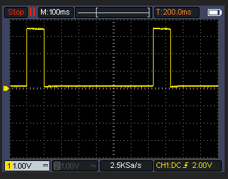
Ich hab mal alles angeschlossen wo sieht man den ob es funktioniert?
-
Ich hab mal alles angeschlossen wo sieht man den ob es funktioniert?
@andy123andy1
"Da wo es qualmt". Sorry aber das klingt sehr "sportlich". Zu Deiner "lwp" nehme an Luftwärmepumpe, sollte sich etwas in deren Handbuch finden lassen und würde empfehlen vorher die erwartbaren Funktionen in Erfahrung zu bringen um keine Schäden & Gefahren zu erzeugen und die Funktion auch Bestimmungsgemäß zu nutzen. -
@andy123andy1
"Da wo es qualmt". Sorry aber das klingt sehr "sportlich". Zu Deiner "lwp" nehme an Luftwärmepumpe, sollte sich etwas in deren Handbuch finden lassen und würde empfehlen vorher die erwartbaren Funktionen in Erfahrung zu bringen um keine Schäden & Gefahren zu erzeugen und die Funktion auch Bestimmungsgemäß zu nutzen.hihi ja so ähnlich.
Ich hab jetzt nochmal gemessen die 20mA kommen bei High an. Das Interval sollte stimmen aber die Luftwärmepume erkennt das Signal nicht. Hab erst mal keine Idee warum nicht.
Vielleicht findet sich noch jemand bei dem es klappt. Vielleicht ist die Spannung zu gering ? Die Klemmen der LWP sind mit 5V beschriftet, wobei das eigentlich egal sein sollte.
Mein Aufbau sieht so aus:
Wemos D1 -> Optokoppler -> + 100 ohm Wiederstand -> LWP
Und ein möglichst einfaches Program aufgespielt. Wärmepume auf 500 Impulse gestellt.
#define S0_PIN D6 // Use the D6 pin on Wemos D1


unsigned long pulseInterval;
float kWh = 1.0; // Default kWh value (example value)
unsigned long pulseDuration = 30; /

void setup() {

  pinMode(S0_PIN, OUTPUT);


  pulseInterval = (3600.0 * 1000.0) / (kWh * 500.0); // 500 pulses per kWh


  Serial.begin(115200);
  while (!Serial) {
    ; // Wait for serial port to connect
  }

  Serial.println("S0 Signal Simulation Started");
  Serial.print("Initial kWh: ");
  Serial.println(kWh);
  Serial.print("Initial pulse interval: ");
  Serial.print(pulseInterval);
  Serial.println(" ms");
}

void loop() {
  unsigned long currentMillis = millis();
  digitalWrite(S0_PIN, HIGH);
  Serial.print("Pulse ON at ");
  Serial.print(currentMillis);
  Serial.println(" ms");
  delay(pulseDuration);

  digitalWrite(S0_PIN, LOW);
  currentMillis = millis();
  Serial.print("Pulse OFF at ");
  Serial.print(currentMillis);
  Serial.println(" ms");
  delay(pulseInterval - pulseDuration);
}
Fall jemand eine Idee hat warum das nicht klappt immer her damit :)
-
hihi ja so ähnlich.
Ich hab jetzt nochmal gemessen die 20mA kommen bei High an. Das Interval sollte stimmen aber die Luftwärmepume erkennt das Signal nicht. Hab erst mal keine Idee warum nicht.
Vielleicht findet sich noch jemand bei dem es klappt. Vielleicht ist die Spannung zu gering ? Die Klemmen der LWP sind mit 5V beschriftet, wobei das eigentlich egal sein sollte.
Mein Aufbau sieht so aus:
Wemos D1 -> Optokoppler -> + 100 ohm Wiederstand -> LWP
Und ein möglichst einfaches Program aufgespielt. Wärmepume auf 500 Impulse gestellt.
#define S0_PIN D6 // Use the D6 pin on Wemos D1


unsigned long pulseInterval;
float kWh = 1.0; // Default kWh value (example value)
unsigned long pulseDuration = 30; /

void setup() {

  pinMode(S0_PIN, OUTPUT);


  pulseInterval = (3600.0 * 1000.0) / (kWh * 500.0); // 500 pulses per kWh


  Serial.begin(115200);
  while (!Serial) {
    ; // Wait for serial port to connect
  }

  Serial.println("S0 Signal Simulation Started");
  Serial.print("Initial kWh: ");
  Serial.println(kWh);
  Serial.print("Initial pulse interval: ");
  Serial.print(pulseInterval);
  Serial.println(" ms");
}

void loop() {
  unsigned long currentMillis = millis();
  digitalWrite(S0_PIN, HIGH);
  Serial.print("Pulse ON at ");
  Serial.print(currentMillis);
  Serial.println(" ms");
  delay(pulseDuration);

  digitalWrite(S0_PIN, LOW);
  currentMillis = millis();
  Serial.print("Pulse OFF at ");
  Serial.print(currentMillis);
  Serial.println(" ms");
  delay(pulseInterval - pulseDuration);
}
Fall jemand eine Idee hat warum das nicht klappt immer her damit :)
@andy123andy1 said in S0 - Signal mit Wemos D1 Mini erzeugen?:
Fall jemand eine Idee hat warum das nicht klappt immer her damit :)
Mein Idee ist den Typ Wärmepumpe mal zu nennen und wenn man nett ist, direkt das Datenblatt/Handbuch zu verlinken. Im Raten bin ich schlecht was dort wo passiert.
-
@andy123andy1 said in S0 - Signal mit Wemos D1 Mini erzeugen?:
Fall jemand eine Idee hat warum das nicht klappt immer her damit :)
Mein Idee ist den Typ Wärmepumpe mal zu nennen und wenn man nett ist, direkt das Datenblatt/Handbuch zu verlinken. Im Raten bin ich schlecht was dort wo passiert.
@dieter_p das ist eine nibe s320
https://www.photovoltaikforum.com/core/attachment/215014-ih-pv-modulsteuerung-allg-pdf/
-
@dieter_p das ist eine nibe s320
https://www.photovoltaikforum.com/core/attachment/215014-ih-pv-modulsteuerung-allg-pdf/
Ich weiß nicht genau was Du vor hast, aber nach dem Handbuch wird über die S0 Schnittstelle der Eigenverbrauchszähler der Wärmepumpe angeklemmt.
PV Erzeugungsdaten kommen per Modbus oder SunSpec Protokoll. Liegen die bereits an?
Heißt vom Prinzip: Dein S0 gibt Vollgas, heißt maximaler Eigenverbrauch und die WP sollte tendentiell irgendwann runterregeln bzw sogar aus bleiben.
Schließt Du gar keinen S0 an, wäre der Eigenverbrauch 0 und somit reagiert die WP "sofort" auf den Bedarf -> schaltet ein/regelt hoch.
Oder wie ist Deine Erwartungshaltung?
-
Ich weiß nicht genau was Du vor hast, aber nach dem Handbuch wird über die S0 Schnittstelle der Eigenverbrauchszähler der Wärmepumpe angeklemmt.
PV Erzeugungsdaten kommen per Modbus oder SunSpec Protokoll. Liegen die bereits an?
Heißt vom Prinzip: Dein S0 gibt Vollgas, heißt maximaler Eigenverbrauch und die WP sollte tendentiell irgendwann runterregeln bzw sogar aus bleiben.
Schließt Du gar keinen S0 an, wäre der Eigenverbrauch 0 und somit reagiert die WP "sofort" auf den Bedarf -> schaltet ein/regelt hoch.
Oder wie ist Deine Erwartungshaltung?
@dieter_p S0 ist der Verbrauch (Lichtstrom) ohne Wäremepumpe. Entsteht ein PV Überschuss soll die anlange die Heiz/ Kühl kurve um 2 verschieben und das Brauchwasser auf "hoch" stellen. So die Idee.
TCP modbus funktioniert.
-
@dieter_p S0 ist der Verbrauch (Lichtstrom) ohne Wäremepumpe. Entsteht ein PV Überschuss soll die anlange die Heiz/ Kühl kurve um 2 verschieben und das Brauchwasser auf "hoch" stellen. So die Idee.
TCP modbus funktioniert.
Ich bin schon mehrfach auf den Thread hereingfallen ...
Könnte der Thread-Ersteller den Thread-Titel etwas ergänzen?S0 ist recht mehrdeutig, mir fiel zuerst ISDN ein, und ich dachte, da wollte jemand mit einem D1 Mini einen VOIP -> ISDN Adapter bauen, um sein altes ISDN-Telefon weiter nutzen zu können ...
Ich weiss .... ich finde die 60 Buchstaben Limitierung für Titel auch nervig ...
-
@dieter_p S0 ist der Verbrauch (Lichtstrom) ohne Wäremepumpe. Entsteht ein PV Überschuss soll die anlange die Heiz/ Kühl kurve um 2 verschieben und das Brauchwasser auf "hoch" stellen. So die Idee.
TCP modbus funktioniert.
@andy123andy1 said in S0 - Signal mit Wemos D1 Mini erzeugen?:
@dieter_p S0 ist der Verbrauch (Lichtstrom) ohne Wäremepumpe. Entsteht ein PV Überschuss soll die anlange die Heiz/ Kühl kurve um 2 verschieben und das Brauchwasser auf "hoch" stellen. So die Idee.
TCP modbus funktioniert.
Ok verstanden.
Wo da die Schaltschwellen inkl. Pufferzeiten liegen kann ich Dir nicht sagen. Das steckt in der Logik dieser Steuerung. Tendentiell würde ich nur keine "HauRuck"-Aktionen der Logik erwarten und andauerndes Takten für solche Vorgänge ist eher schädlich. Du schaltest immerhin 11kW im Worst-Case.
Das muß erstmal vom Dach kommen.
Daher würde ich bei so einer Simulation den Verbrauch des sonstigen Haushaltstroms eher zum Testen runter setzen und Du simlierst doch gerade eine Dauerlast (Haushaltsstrom) von 1kW. Das finde ich schon heftig und bin bei mir eher bei 0,25kW. Kommt natürlich auch darauf an was gerade von Deinem Dach kommt und welche Leistung die WP zieht. -
@andy123andy1 said in S0 - Signal mit Wemos D1 Mini erzeugen?:
@dieter_p S0 ist der Verbrauch (Lichtstrom) ohne Wäremepumpe. Entsteht ein PV Überschuss soll die anlange die Heiz/ Kühl kurve um 2 verschieben und das Brauchwasser auf "hoch" stellen. So die Idee.
TCP modbus funktioniert.
Ok verstanden.
Wo da die Schaltschwellen inkl. Pufferzeiten liegen kann ich Dir nicht sagen. Das steckt in der Logik dieser Steuerung. Tendentiell würde ich nur keine "HauRuck"-Aktionen der Logik erwarten und andauerndes Takten für solche Vorgänge ist eher schädlich. Du schaltest immerhin 11kW im Worst-Case.
Das muß erstmal vom Dach kommen.
Daher würde ich bei so einer Simulation den Verbrauch des sonstigen Haushaltstroms eher zum Testen runter setzen und Du simlierst doch gerade eine Dauerlast (Haushaltsstrom) von 1kW. Das finde ich schon heftig und bin bei mir eher bei 0,25kW. Kommt natürlich auch darauf an was gerade von Deinem Dach kommt und welche Leistung die WP zieht.@dieter_p Genau um dabei sicher zu sein hätte ich, wenn es funktioniert, den akutellen Lichtstrom-Verbrauch auf den Adurino/S0 geschrieben. Die Logik der Wärmepumpe hätte dann die Kontrolle über die Taktung. Die alternative wäre per tcp-modbus der LWP die Wert (wasser hoch/ kurve +-2) zu setzen. Dadurch würde man aber über die Taktung selbst entscheiden.
Im Moment habe ich einfach eine Zeitsteuerung der LWP von 22:00-08:00 Uhr alles blockiert und von 14:00-17:00 Uhr Brauchwasser hoch.
Ohne den S0 macht die LWP mit den werten der PV Anlage nix.
-
@dieter_p Genau um dabei sicher zu sein hätte ich, wenn es funktioniert, den akutellen Lichtstrom-Verbrauch auf den Adurino/S0 geschrieben. Die Logik der Wärmepumpe hätte dann die Kontrolle über die Taktung. Die alternative wäre per tcp-modbus der LWP die Wert (wasser hoch/ kurve +-2) zu setzen. Dadurch würde man aber über die Taktung selbst entscheiden.
Im Moment habe ich einfach eine Zeitsteuerung der LWP von 22:00-08:00 Uhr alles blockiert und von 14:00-17:00 Uhr Brauchwasser hoch.
Ohne den S0 macht die LWP mit den werten der PV Anlage nix.
Mit einem Adurino UNO klappt es sofort. Allerdings hab ich ein Verständnis Problem der Zähler der LWP zählt nur nach oben. Ich dachte da soll der aktuelle verbrauchte Stromverbrauch abgebildet werden. Um eben die Differenz aus PV Strom und aktuell verbrauchten Strom zu bilden.
edit
Daraus kann man dann den aktuellen Strom verbrauch errechnen okay :)Frag mich nur gerade ob der Aufwand dem Nutzen wert ist. Ich müsste jetzt den Wechselrichter fragen wie viel Strom verbracht das Haus, dann die LWP wie viel verbrauchst du. Daraus die Differenz bilden und warten bis eine kWh erreicht ist. Diese Information müsste ich dann dem Adurino geben der wiederum den S0 Eingang der LWP anspricht.
-
@andy123andy1 said in S0 - Signal mit Wemos D1 Mini erzeugen?:
@dieter_p S0 ist der Verbrauch (Lichtstrom) ohne Wäremepumpe. Entsteht ein PV Überschuss soll die anlange die Heiz/ Kühl kurve um 2 verschieben und das Brauchwasser auf "hoch" stellen. So die Idee.
TCP modbus funktioniert.
Ok verstanden.
Wo da die Schaltschwellen inkl. Pufferzeiten liegen kann ich Dir nicht sagen. Das steckt in der Logik dieser Steuerung. Tendentiell würde ich nur keine "HauRuck"-Aktionen der Logik erwarten und andauerndes Takten für solche Vorgänge ist eher schädlich. Du schaltest immerhin 11kW im Worst-Case.
Das muß erstmal vom Dach kommen.
Daher würde ich bei so einer Simulation den Verbrauch des sonstigen Haushaltstroms eher zum Testen runter setzen und Du simlierst doch gerade eine Dauerlast (Haushaltsstrom) von 1kW. Das finde ich schon heftig und bin bei mir eher bei 0,25kW. Kommt natürlich auch darauf an was gerade von Deinem Dach kommt und welche Leistung die WP zieht.@dieter_p said in S0 - Signal mit Wemos D1 Mini erzeugen?:
@andy123andy1 said in S0 - Signal mit Wemos D1 Mini erzeugen?:
@dieter_p S0 ist der Verbrauch (Lichtstrom) ohne Wäremepumpe. Entsteht ein PV Überschuss soll die anlange die Heiz/ Kühl kurve um 2 verschieben und das Brauchwasser auf "hoch" stellen. So die Idee.
TCP modbus funktioniert.
Ok verstanden.
Wo da die Schaltschwellen inkl. Pufferzeiten liegen kann ich Dir nicht sagen. Das steckt in der Logik dieser Steuerung. Tendentiell würde ich nur keine "HauRuck"-Aktionen der Logik erwarten und andauerndes Takten für solche Vorgänge ist eher schädlich. Du schaltest immerhin 11kW im Worst-Case.
Das muß erstmal vom Dach kommen.
Daher würde ich bei so einer Simulation den Verbrauch des sonstigen Haushaltstroms eher zum Testen runter setzen und Du simlierst doch gerade eine Dauerlast (Haushaltsstrom) von 1kW. Das finde ich schon heftig und bin bei mir eher bei 0,25kW. Kommt natürlich auch darauf an was gerade von Deinem Dach kommt und welche Leistung die WP zieht.Ich hatte das so Verstanden: Wenn das Haus 1kWH verbaucht wird dieser vom Überschuss abgezogen. Heißt wenn 6kwH Überschuss vorhanden sind kann die LWP nur 5kwH verwenden. Ich würde den Wert sogar auf 2kWH setzen dann ist man vermutlich zu 90% auf der sicheren Seite. Wenn von der PV Anlage 8 kWH kommen werden 2 kWH abgezogen. Bleiben also 4kWH für die LWP. Wenn keine Sonne scheint oder die Leistung der PV Anlage nicht über 2kWH steigt wird eben nichts optimiert. Zumindest so mein Verständnis.
Hey! Du scheinst an dieser Unterhaltung interessiert zu sein, hast aber noch kein Konto.
Hast du es satt, bei jedem Besuch durch die gleichen Beiträge zu scrollen? Wenn du dich für ein Konto anmeldest, kommst du immer genau dorthin zurück, wo du zuvor warst, und kannst dich über neue Antworten benachrichtigen lassen (entweder per E-Mail oder Push-Benachrichtigung). Du kannst auch Lesezeichen speichern und Beiträge positiv bewerten, um anderen Community-Mitgliedern deine Wertschätzung zu zeigen.
Mit deinem Input könnte dieser Beitrag noch besser werden 💗
Registrieren AnmeldenSupport us
236
Online33.0k
Benutzer83.4k
Themen1.3m
Beiträge