

S0 - Signal mit Wemos D1 Mini erzeugen?
-
Ich habe dies inzwischen noch mit einem Labornetzteil bei 27Volt und mit einem Oszi über den 1000 Ohm Widerstand getestet (R3 im LTSPice Modell). Und mit jeweils 200 Ohm Widerständen bei R1 und R2.
Mit dem Oszi messe ich damit über R3 ca. 18.5V während des "high signals" ("Ein-Zustand"), damit ca. 18.5mA.
Ich vermute, dass dies ziemlich gut sein dürfte (da während des "Ein-Zustands" für Klasse deutlich über den minimalen 10mA und auch unter den maximalen 27mA; und da damit auch nur ca. 10mA über R2 und damit am GPIO des ESP32).
Ich vermute, dass dies gut sein dürfte, sonst bitte Feedback.
Vielen Dank!
P.S.: Gemäss meinem oberen LTSpice Modell wäre dies als Strom über R3 dort ca. 16.5mA (gemessen: 18.5mA). Ca. 10% Abweichung finde ich nachvollziehbar, insbesondere da ich denke, dass es wahrscheinlich unterschiedliche Modelle und auch etwas Toleranz insbesondere beim Optokoppler geben dürfte. -
@dieter_p
Vielen Dank!
Ja, korrekt, die Genauigkeit ist mit "TOL: ±1%" angegeben.
Ich habe mir jedoch ein Set gekauft, da ich den Strom mit verschiedenen Widerständen messen wollte. Und bei vielen Sets waren z.B. 220 Ohm, aber nicht 200 Ohm Widerstände dabei. Daher habe ich dies nach den Widerstandsgrössen ausgewählt, die im Set dabei sind, und nicht nach der Genauigkeit. Dies habe ich erst jetzt nachgeschaut. -
@dieter_p
Vielen Dank!
Ja, korrekt, die Genauigkeit ist mit "TOL: ±1%" angegeben.
Ich habe mir jedoch ein Set gekauft, da ich den Strom mit verschiedenen Widerständen messen wollte. Und bei vielen Sets waren z.B. 220 Ohm, aber nicht 200 Ohm Widerstände dabei. Daher habe ich dies nach den Widerstandsgrössen ausgewählt, die im Set dabei sind, und nicht nach der Genauigkeit. Dies habe ich erst jetzt nachgeschaut.@mistral
War für mich nur eine Option um die Schwankung von 10% etwas erklärbarer zu machen. 5% Widerstände dürften wohl kaum noch zum Einsatz kommen und da hätte man ggf etwas optimieren können indem du die Widerstände vorher ausmist und wählst. Aber bei 1% kann man sich das schenken ;)Klingt gut, lass mal wissen wenn es in Funktion läuft.
-
@mistral
War für mich nur eine Option um die Schwankung von 10% etwas erklärbarer zu machen. 5% Widerstände dürften wohl kaum noch zum Einsatz kommen und da hätte man ggf etwas optimieren können indem du die Widerstände vorher ausmist und wählst. Aber bei 1% kann man sich das schenken ;)Klingt gut, lass mal wissen wenn es in Funktion läuft.
@dieter_p
Vielen Dank und ja, werde mich dann gerne wieder melden. Bis es läuft, wird es wahrscheinlich noch etwas dauern: Ich warte noch auf das PCB, welches ich dafür erstellt und bestellt habe (aktuell erst auf einem breadboard) und noch auf ein paar kleinere Komponenten.
Betreffs Schwankung gehe ich ziemlich sicher vom Optokoppler aus: Dort ist für den 4N35 bei LTSpice keine Komponente direkt dabei und ich musste dies daher im Internet suchen. Und mein 4N35 Optokoppler hatte ich bei mir bereits "herumliegen" und weiss auch nicht, von welchem Hersteller dieser ist. -
@mistral
War für mich nur eine Option um die Schwankung von 10% etwas erklärbarer zu machen. 5% Widerstände dürften wohl kaum noch zum Einsatz kommen und da hätte man ggf etwas optimieren können indem du die Widerstände vorher ausmist und wählst. Aber bei 1% kann man sich das schenken ;)Klingt gut, lass mal wissen wenn es in Funktion läuft.
@dieter_p Ist jetzt in Funktion und läuft :-)
Wie gut die Regelung seitens der WP ist, kann ich noch nicht beurteilen, aber das S0 Signal wird bei mir einwandfrei übermittelt und anhand der aktuellen PV Einspeiseleistung berechnet.
Vielen Dank! -
@dieter_p Ist jetzt in Funktion und läuft :-)
Wie gut die Regelung seitens der WP ist, kann ich noch nicht beurteilen, aber das S0 Signal wird bei mir einwandfrei übermittelt und anhand der aktuellen PV Einspeiseleistung berechnet.
Vielen Dank!@mistral Guten Morgen, ich suche gerade auch nach einer Lösung ein S0 Signal zu erzeugen. Kannst du die verwendetet Hardware und evtl. den Code der Öffentlichkeit zur Verfügung stellen? Dann brauche ich nicht alles neu Recherchieren und Testen :)
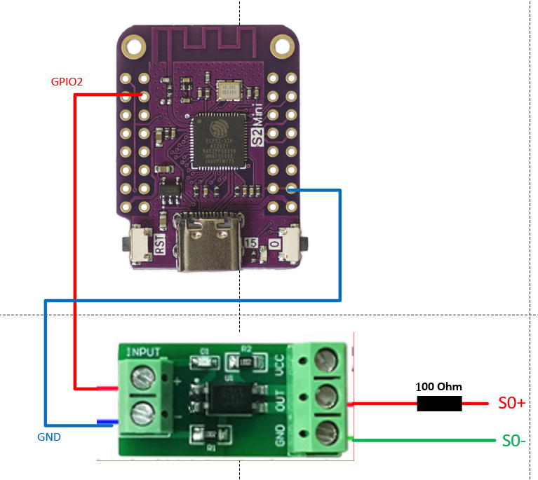
Das ist die benötigte Hardware wenn ich es richtig aus den vorherigen Post lese:
Wenn jetzt noch jemand einen Code Schnipsel hätte wäre ich glücklich :)
Hab mal rumprobiert hier mein Ergebnis:
#include <ESP8266WiFi.h>
#include <PubSubClient.h>

// WiFi configuration
const char* ssid = "your_SSID";
const char* password = "your_PASSWORD";

// MQTT configuration
const char* mqtt_server = "broker_address";
const char* mqtt_topic = "energy/consumption";
const int mqtt_port = 1883;

// S0 Pin configuration
const int s0Pin = 7; // Pin connected to the S0 output signal

// Timing variables
unsigned long pulseDuration = 100; // Duration of each pulse in milliseconds
unsigned long pulseInterval = 720; // Interval between pulses in milliseconds (initial value)

// WiFi and MQTT clients
WiFiClient espClient;
PubSubClient client(espClient);

// Function to handle received MQTT messages
void callback(char* topic, byte* payload, unsigned int length) {
  char message[length + 1];
  strncpy(message, (char*)payload, length);
  message[length] = '\0';

  float kWh = atof(message); // Convert received message to float

  // Assuming 1000 pulses per kWh and 3600 seconds in an hour
  pulseInterval = (3600 * 1000) / (kWh * 1000) - pulseDuration;
}

void setup() {
  // Set the S0 pin as an output
  pinMode(s0Pin, OUTPUT);

  // Initialize Serial for debugging
  Serial.begin(115200);

  // Connect to WiFi
  setup_wifi();

  // Set up MQTT client
  client.setServer(mqtt_server, mqtt_port);
  client.setCallback(callback);

  // Connect to MQTT broker
  reconnect();
}

void loop() {
  if (!client.connected()) {
    reconnect();
  }
  client.loop();

  // Generate a pulse
  digitalWrite(s0Pin, HIGH);  // Set the S0 pin HIGH
  delay(pulseDuration);       // Wait for the pulse duration
  digitalWrite(s0Pin, LOW);   // Set the S0 pin LOW
  delay(pulseInterval);       // Wait for the interval before the next pulse
}

void setup_wifi() {
  delay(10);
  // Connect to WiFi
  Serial.println();
  Serial.print("Connecting to ");
  Serial.println(ssid);

  WiFi.begin(ssid, password);

  while (WiFi.status() != WL_CONNECTED) {
    delay(500);
    Serial.print(".");
  }

  Serial.println("");
  Serial.println("WiFi connected");
  Serial.println("IP address: ");
  Serial.println(WiFi.localIP());
}

void reconnect() {
  // Loop until we're reconnected
  while (!client.connected()) {
    Serial.print("Attempting MQTT connection...");
    // Attempt to connect
    if (client.connect("ESP8266Client")) {
      Serial.println("connected");
      // Subscribe to topic
      client.subscribe(mqtt_topic);
    } else {
      Serial.print("failed, rc=");
      Serial.print(client.state());
      Serial.println(" try again in 5 seconds");
      // Wait 5 seconds before retrying
      delay(5000);
    }
  }
}
Hab leider kein Oszilloskop um das mal zu prüfen.
-
@mistral Guten Morgen, ich suche gerade auch nach einer Lösung ein S0 Signal zu erzeugen. Kannst du die verwendetet Hardware und evtl. den Code der Öffentlichkeit zur Verfügung stellen? Dann brauche ich nicht alles neu Recherchieren und Testen :)
Das ist die benötigte Hardware wenn ich es richtig aus den vorherigen Post lese:
Wenn jetzt noch jemand einen Code Schnipsel hätte wäre ich glücklich :)
Hab mal rumprobiert hier mein Ergebnis:
#include <ESP8266WiFi.h>
#include <PubSubClient.h>

// WiFi configuration
const char* ssid = "your_SSID";
const char* password = "your_PASSWORD";

// MQTT configuration
const char* mqtt_server = "broker_address";
const char* mqtt_topic = "energy/consumption";
const int mqtt_port = 1883;

// S0 Pin configuration
const int s0Pin = 7; // Pin connected to the S0 output signal

// Timing variables
unsigned long pulseDuration = 100; // Duration of each pulse in milliseconds
unsigned long pulseInterval = 720; // Interval between pulses in milliseconds (initial value)

// WiFi and MQTT clients
WiFiClient espClient;
PubSubClient client(espClient);

// Function to handle received MQTT messages
void callback(char* topic, byte* payload, unsigned int length) {
  char message[length + 1];
  strncpy(message, (char*)payload, length);
  message[length] = '\0';

  float kWh = atof(message); // Convert received message to float

  // Assuming 1000 pulses per kWh and 3600 seconds in an hour
  pulseInterval = (3600 * 1000) / (kWh * 1000) - pulseDuration;
}

void setup() {
  // Set the S0 pin as an output
  pinMode(s0Pin, OUTPUT);

  // Initialize Serial for debugging
  Serial.begin(115200);

  // Connect to WiFi
  setup_wifi();

  // Set up MQTT client
  client.setServer(mqtt_server, mqtt_port);
  client.setCallback(callback);

  // Connect to MQTT broker
  reconnect();
}

void loop() {
  if (!client.connected()) {
    reconnect();
  }
  client.loop();

  // Generate a pulse
  digitalWrite(s0Pin, HIGH);  // Set the S0 pin HIGH
  delay(pulseDuration);       // Wait for the pulse duration
  digitalWrite(s0Pin, LOW);   // Set the S0 pin LOW
  delay(pulseInterval);       // Wait for the interval before the next pulse
}

void setup_wifi() {
  delay(10);
  // Connect to WiFi
  Serial.println();
  Serial.print("Connecting to ");
  Serial.println(ssid);

  WiFi.begin(ssid, password);

  while (WiFi.status() != WL_CONNECTED) {
    delay(500);
    Serial.print(".");
  }

  Serial.println("");
  Serial.println("WiFi connected");
  Serial.println("IP address: ");
  Serial.println(WiFi.localIP());
}

void reconnect() {
  // Loop until we're reconnected
  while (!client.connected()) {
    Serial.print("Attempting MQTT connection...");
    // Attempt to connect
    if (client.connect("ESP8266Client")) {
      Serial.println("connected");
      // Subscribe to topic
      client.subscribe(mqtt_topic);
    } else {
      Serial.print("failed, rc=");
      Serial.print(client.state());
      Serial.println(" try again in 5 seconds");
      // Wait 5 seconds before retrying
      delay(5000);
    }
  }
}
Hab leider kein Oszilloskop um das mal zu prüfen.
-
Hab leider kein Oszilloskop um das mal zu prüfen.
Wenn Du mir einen "easy" weg erklärst wie ich das in den ESP32 reinbekomme, schließe ich mal ein Oszi dran an.
@dieter_p Ich würde das mit Adurino IDE auf einen ESP flashen.
Hier der Code vereinfacht und ohne Wifi & MQTT. Das sollte jetzt 5kwH abbilden.
// S0 Pin configuration const int s0Pin = 7; // Pin connected to the S0 output signal // Timing variables unsigned long pulseDuration = 100; // Duration of each pulse in milliseconds // replaced with static value unsigned long pulseInterval = (3600 * 1000) / (5 * 1000) - pulseDuration; // Interval between pulses in milliseconds (initial value) void setup() { // Set the S0 pin as an output pinMode(s0Pin, OUTPUT); // Initialize Serial for debugging Serial.begin(115200); } void loop() { // Generate a pulse digitalWrite(s0Pin, HIGH); // Set the S0 pin HIGH delay(pulseDuration); // Wait for the pulse duration digitalWrite(s0Pin, LOW); // Set the S0 pin LOW delay(pulseInterval); // Wait for the interval before the next pulse } -
@dieter_p Ich würde das mit Adurino IDE auf einen ESP flashen.
Hier der Code vereinfacht und ohne Wifi & MQTT. Das sollte jetzt 5kwH abbilden.
// S0 Pin configuration const int s0Pin = 7; // Pin connected to the S0 output signal // Timing variables unsigned long pulseDuration = 100; // Duration of each pulse in milliseconds // replaced with static value unsigned long pulseInterval = (3600 * 1000) / (5 * 1000) - pulseDuration; // Interval between pulses in milliseconds (initial value) void setup() { // Set the S0 pin as an output pinMode(s0Pin, OUTPUT); // Initialize Serial for debugging Serial.begin(115200); } void loop() { // Generate a pulse digitalWrite(s0Pin, HIGH); // Set the S0 pin HIGH delay(pulseDuration); // Wait for the pulse duration digitalWrite(s0Pin, LOW); // Set the S0 pin LOW delay(pulseInterval); // Wait for the interval before the next pulse }@andy123andy1 said in S0 - Signal mit Wemos D1 Mini erzeugen?:
@dieter_p Ich würde das mit Adurino IDE auf einen ESP flashen.
Bin Tasmota/ESPEasy verseucht, aber wird man ja nicht dümmer durch etwas Neues zu probieren. Starte mal bei mir die Umgebung aufzusetzen und melde mich.
Alternativ die "dumme" Frage eine .bin datei daraus kannst Du mir nicht erzeugen und ich flashe sie einfach auf den ESP?
-
@andy123andy1 said in S0 - Signal mit Wemos D1 Mini erzeugen?:
@dieter_p Ich würde das mit Adurino IDE auf einen ESP flashen.
Bin Tasmota/ESPEasy verseucht, aber wird man ja nicht dümmer durch etwas Neues zu probieren. Starte mal bei mir die Umgebung aufzusetzen und melde mich.
Alternativ die "dumme" Frage eine .bin datei daraus kannst Du mir nicht erzeugen und ich flashe sie einfach auf den ESP?
Doch das geht ich müsste nur welchen welchen ESP.
-
Doch das geht ich müsste nur welchen welchen ESP.
Hab einen ESP32 S2 hier (wie auf der Zeichnung/Screenshot)
Edit: den configurierten S0 Pin hast Du in der letzten Version rausgenommen, bleibt bei GPIO 7 ?
-
Hab einen ESP32 S2 hier (wie auf der Zeichnung/Screenshot)
Edit: den configurierten S0 Pin hast Du in der letzten Version rausgenommen, bleibt bei GPIO 7 ?
-
kann keine Funktion/Signalpuls messen
Hab zum Test nochmal ESPEasy zum Vergleich genutzt und hier lässt sich ein Puls messen.
-
kann keine Funktion/Signalpuls messen
Hab zum Test nochmal ESPEasy zum Vergleich genutzt und hier lässt sich ein Puls messen.
Komisch nochmal das gleiche mit PIN 2
-
Komisch nochmal das gleiche mit PIN 2
bisher nein und mit ESPEasy alles wie gehabt:
Der ESP32S2 ist am seriellen Anschluß etwas speziell, daher sehe ich im Moment keine Log/Terminal Daten ob er überhaupt startet.
Gucke mal ob ich was anderes hier hab.
-
@dieter_p Ich würde das mit Adurino IDE auf einen ESP flashen.
Hier der Code vereinfacht und ohne Wifi & MQTT. Das sollte jetzt 5kwH abbilden.
// S0 Pin configuration const int s0Pin = 7; // Pin connected to the S0 output signal // Timing variables unsigned long pulseDuration = 100; // Duration of each pulse in milliseconds // replaced with static value unsigned long pulseInterval = (3600 * 1000) / (5 * 1000) - pulseDuration; // Interval between pulses in milliseconds (initial value) void setup() { // Set the S0 pin as an output pinMode(s0Pin, OUTPUT); // Initialize Serial for debugging Serial.begin(115200); } void loop() { // Generate a pulse digitalWrite(s0Pin, HIGH); // Set the S0 pin HIGH delay(pulseDuration); // Wait for the pulse duration digitalWrite(s0Pin, LOW); // Set the S0 pin LOW delay(pulseInterval); // Wait for the interval before the next pulse }@andy123andy1 said in S0 - Signal mit Wemos D1 Mini erzeugen?:
// S0 Pin configuration
const int s0Pin = 7; // Pin connected to the S0 output signal// Timing variables
unsigned long pulseDuration = 100; // Duration of each pulse in milliseconds
// replaced with static value
unsigned long pulseInterval = (3600 * 1000) / (5 * 1000) - pulseDuration; // Interval between pulses in milliseconds (initial value)void setup() {
// Set the S0 pin as an output
pinMode(s0Pin, OUTPUT);// Initialize Serial for debugging
Serial.begin(115200);
}void loop() {
// Generate a pulse
digitalWrite(s0Pin, HIGH); // Set the S0 pin HIGH
delay(pulseDuration); // Wait for the pulse duration
digitalWrite(s0Pin, LOW); // Set the S0 pin LOW
delay(pulseInterval); // Wait for the interval before the next pulse
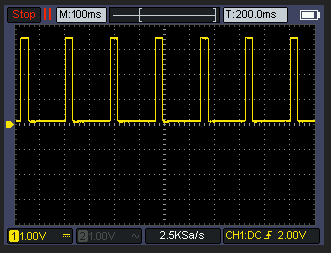
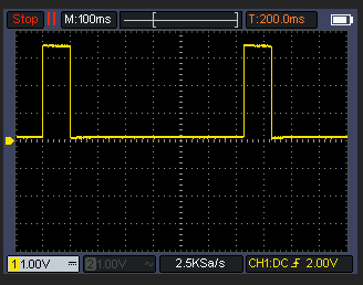
}So, hab das mal selbst unter Adruino IDE auf den ESP geladen.
Funtioniert:
-
@andy123andy1 said in S0 - Signal mit Wemos D1 Mini erzeugen?:
// S0 Pin configuration
const int s0Pin = 7; // Pin connected to the S0 output signal// Timing variables
unsigned long pulseDuration = 100; // Duration of each pulse in milliseconds
// replaced with static value
unsigned long pulseInterval = (3600 * 1000) / (5 * 1000) - pulseDuration; // Interval between pulses in milliseconds (initial value)void setup() {
// Set the S0 pin as an output
pinMode(s0Pin, OUTPUT);// Initialize Serial for debugging
Serial.begin(115200);
}void loop() {
// Generate a pulse
digitalWrite(s0Pin, HIGH); // Set the S0 pin HIGH
delay(pulseDuration); // Wait for the pulse duration
digitalWrite(s0Pin, LOW); // Set the S0 pin LOW
delay(pulseInterval); // Wait for the interval before the next pulse
}So, hab das mal selbst unter Adruino IDE auf den ESP geladen.
Funtioniert:
Richtig cool. Dann kann man dem code von oben und dem bischen Hardware sich das s0 signal für die lwp bauen. Ich hab mal 3 von den PC817 bestellt und werde mal testen, ob die lwp was versteht.
-
Richtig cool. Dann kann man dem code von oben und dem bischen Hardware sich das s0 signal für die lwp bauen. Ich hab mal 3 von den PC817 bestellt und werde mal testen, ob die lwp was versteht.
Kleines update das ist jetzt das finale "script" auf einem Adurino Nano. Der sendet pauschal 2kwH an die LWP. Man kann wenn man will über eine USB/Serial Verbindung die richtige kwH in Fließkomma (1.3 etc) setzen. Bei mir hängt der Nano am USB vom "NAS".
const int s0Pin = 7; // Pin connected to the S0 output signal

// Timing variables
unsigned long pulseDuration = 100; // Duration of each pulse in milliseconds
unsigned long pulseInterval = 3500; // Interval between pulses in milliseconds (initial value)
float kWh = 1.0; // Initial kWh value

unsigned long previousMillis = 0; // Store the last time a pulse was generated
unsigned long pulseEndMillis = 0; // Store the end time of the pulse
bool pulseActive = false; // Flag to track pulse state

void setup() {
  // Set the S0 pin as an output
  pinMode(s0Pin, OUTPUT);

  // Initialize Serial for communication
  Serial.begin(115200);
  while (!Serial) {
    ; // Wait for the serial port to connect. Needed for native USB port only
  }

  Serial.println("Enter kWh value:");
}

void loop() {
  // Check if data is available on the serial port
  if (Serial.available() > 0) {
    String input = Serial.readStringUntil('\n'); // Read the input
    kWh = input.toFloat(); // Convert input to float

    if (kWh > 0) {
      // Calculate pulse interval based on kWh value
      pulseInterval = (3600.0 * 1000.0) / (kWh * 1000.0) - pulseDuration;
      Serial.print("Updated kWh: ");
      Serial.println(kWh);
      Serial.print("Updated pulse interval: ");
      Serial.println(pulseInterval);
    }
  }

  unsigned long currentMillis = millis();

  // Check if it's time to generate a new pulse
  if (currentMillis - previousMillis >= pulseInterval && !pulseActive) {
    // Save the last time a pulse was started
    previousMillis = currentMillis;

    // Start the pulse
    digitalWrite(s0Pin, HIGH);
    pulseEndMillis = currentMillis + pulseDuration;
    pulseActive = true;
  }

  // Check if it's time to end the pulse
  if (pulseActive && currentMillis >= pulseEndMillis) {
    digitalWrite(s0Pin, LOW);
    pulseActive = false;
  }
}
senden vom pc aus könnte so aussehen:
import serial import time # Configure the serial port and baud rate ser = serial.Serial('/dev/ttyUSB0', 115200) # Change 'COM3' to the appropriate port for your system time.sleep(2) # Give some time to establish the connection def send_kwh_value(kwh): ser.write(f"{kwh}\n".encode()) # Send kWh value as a string with newline time.sleep(1) # Give some time for the Arduino to process and respond # Read response lines from the serial port response_lines = [] while ser.in_waiting > 0: line = ser.readline().decode('utf-8').rstrip() response_lines.append(line) return response_lines # Example usage response = send_kwh_value(5.0) # Send 5.0 kWh value for line in response: print(line) ser.close() -
Kleines update das ist jetzt das finale "script" auf einem Adurino Nano. Der sendet pauschal 2kwH an die LWP. Man kann wenn man will über eine USB/Serial Verbindung die richtige kwH in Fließkomma (1.3 etc) setzen. Bei mir hängt der Nano am USB vom "NAS".
const int s0Pin = 7; // Pin connected to the S0 output signal

// Timing variables
unsigned long pulseDuration = 100; // Duration of each pulse in milliseconds
unsigned long pulseInterval = 3500; // Interval between pulses in milliseconds (initial value)
float kWh = 1.0; // Initial kWh value

unsigned long previousMillis = 0; // Store the last time a pulse was generated
unsigned long pulseEndMillis = 0; // Store the end time of the pulse
bool pulseActive = false; // Flag to track pulse state

void setup() {
  // Set the S0 pin as an output
  pinMode(s0Pin, OUTPUT);

  // Initialize Serial for communication
  Serial.begin(115200);
  while (!Serial) {
    ; // Wait for the serial port to connect. Needed for native USB port only
  }

  Serial.println("Enter kWh value:");
}

void loop() {
  // Check if data is available on the serial port
  if (Serial.available() > 0) {
    String input = Serial.readStringUntil('\n'); // Read the input
    kWh = input.toFloat(); // Convert input to float

    if (kWh > 0) {
      // Calculate pulse interval based on kWh value
      pulseInterval = (3600.0 * 1000.0) / (kWh * 1000.0) - pulseDuration;
      Serial.print("Updated kWh: ");
      Serial.println(kWh);
      Serial.print("Updated pulse interval: ");
      Serial.println(pulseInterval);
    }
  }

  unsigned long currentMillis = millis();

  // Check if it's time to generate a new pulse
  if (currentMillis - previousMillis >= pulseInterval && !pulseActive) {
    // Save the last time a pulse was started
    previousMillis = currentMillis;

    // Start the pulse
    digitalWrite(s0Pin, HIGH);
    pulseEndMillis = currentMillis + pulseDuration;
    pulseActive = true;
  }

  // Check if it's time to end the pulse
  if (pulseActive && currentMillis >= pulseEndMillis) {
    digitalWrite(s0Pin, LOW);
    pulseActive = false;
  }
}
senden vom pc aus könnte so aussehen:
import serial import time # Configure the serial port and baud rate ser = serial.Serial('/dev/ttyUSB0', 115200) # Change 'COM3' to the appropriate port for your system time.sleep(2) # Give some time to establish the connection def send_kwh_value(kwh): ser.write(f"{kwh}\n".encode()) # Send kWh value as a string with newline time.sleep(1) # Give some time for the Arduino to process and respond # Read response lines from the serial port response_lines = [] while ser.in_waiting > 0: line = ser.readline().decode('utf-8').rstrip() response_lines.append(line) return response_lines # Example usage response = send_kwh_value(5.0) # Send 5.0 kWh value for line in response: print(line) ser.close()Bist Du sicher das es hier nicht um die Leistung -> W geht?
-
Bist Du sicher das es hier nicht um die Leistung -> W geht?
Hey! Du scheinst an dieser Unterhaltung interessiert zu sein, hast aber noch kein Konto.
Hast du es satt, bei jedem Besuch durch die gleichen Beiträge zu scrollen? Wenn du dich für ein Konto anmeldest, kommst du immer genau dorthin zurück, wo du zuvor warst, und kannst dich über neue Antworten benachrichtigen lassen (entweder per E-Mail oder Push-Benachrichtigung). Du kannst auch Lesezeichen speichern und Beiträge positiv bewerten, um anderen Community-Mitgliedern deine Wertschätzung zu zeigen.
Mit deinem Input könnte dieser Beitrag noch besser werden 💗
Registrieren AnmeldenSupport us
232
Online33.0k
Benutzer83.4k
Themen1.3m
Beiträge